Fire alarm systems are designed for early detection of fire, smoke, flames, gas or carbon monoxide giving us time to evacuate safely. Early detection is also key to protecting life and property and giving emergency responders enough time to provide timely assistance while a fire or toxic gas is still small.
In this article, the company P69 will delve into the structure, diagram, operating principle and common automatic fire alarm systems on the market.
What is a fire alarm system?
Fire alarm systems are designed to alert us in an emergency so we can take action to protect ourselves, our families, our employees and everyone else.
- Protection mechanism: detection of fires, smoke, sudden temperature rise, leakage of toxic gas, gas, carbon monoxide.
- Warning mechanism: siren, flashing lights, emergency call.
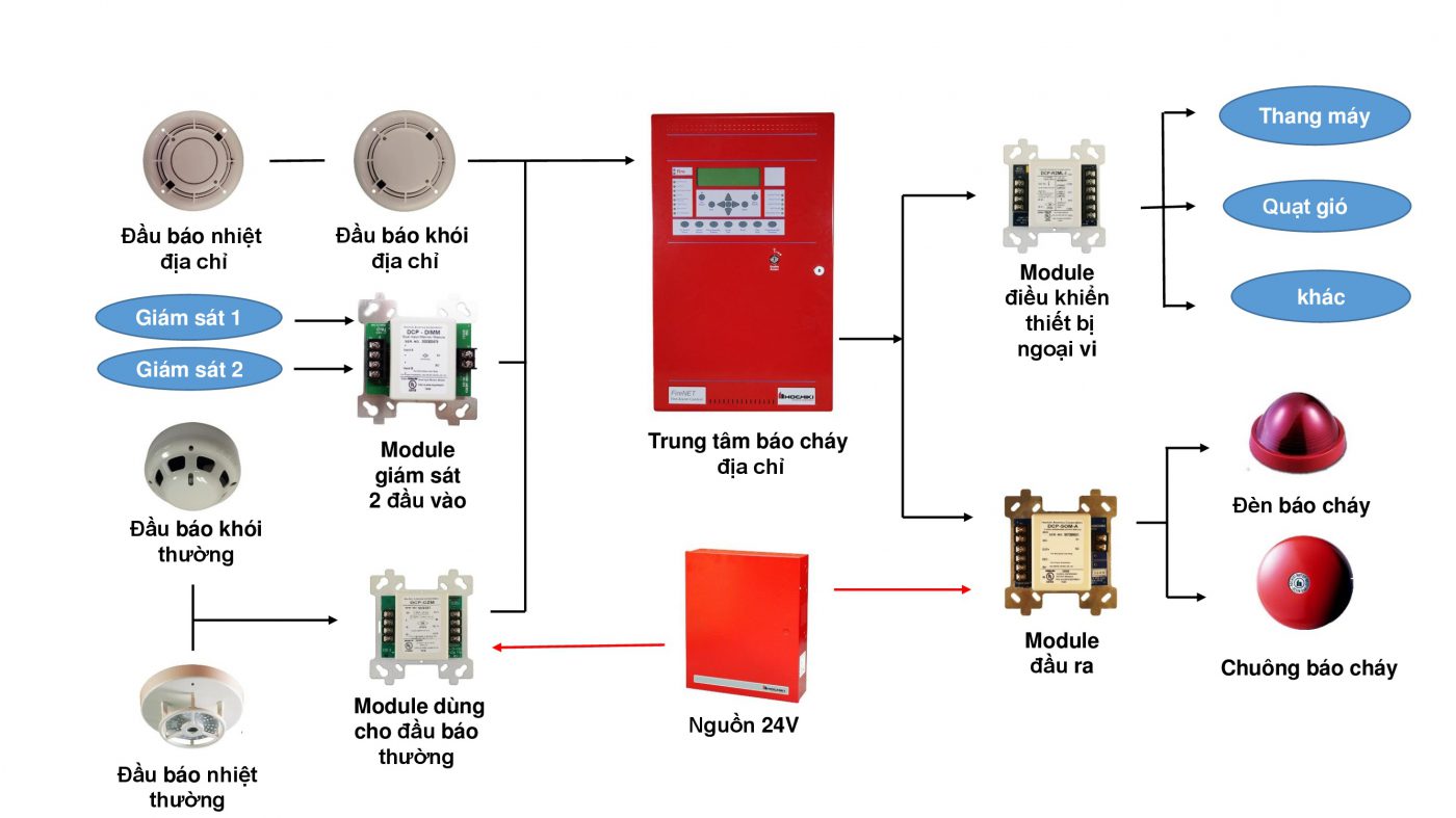
Construction of automatic fire alarm system
An automatic fire alarm system consists of 03 main components which are fire alarm center, input sensor and output warning device.
The central fire alarm cabinet is designed in the form of a cabinet, has a backup battery and has phone SIM modules for emergency dialing.
– Sensor (initiating devices) : is a system of sensor probes responsible for detecting fires or smoke. Includes smoke detector, heat detector, gas detector, carbon monoxide detector and emergency push button. The sensor probes will be wired to the fire alarm center.
– Fire alarm center (central processing unit) : receiving, analyzing and processing signals from incoming sensor probes.
– Loudspeakers, fire alarms (output devices) : are fire alarm devices such as fire alarms, fire alarm loudspeakers, emergency dialers.
Working principle of fire alarm system
– Step 1: When the sensors detect a fire, rising temperature, smoke or toxic gas… they immediately send a signal to the central fire alarm cabinet. The same thing happens if the user presses the emergency button.
– Step 2 : Fire alarm control panel (FACP) is the main control component of fire alarm devices. When receiving the fire alarm signal from the detector or the emergency button, the fire alarm cabinet will send a signal to the emergency alarm device (horn, light…).
– Step 3: Alarm devices include:
- Fire sirens, fire loudspeakers, flashing lights, sirens: warn people to evacuate.
- Emergency dialing module: make a call to the functional force (fire 114) or to the person in charge to handle it.
Schematic drawing of the fire alarm system
Currently, there are two drawings of the principle diagram of the fire alarm system that are most commonly applied: the principle diagram of the conventional fire alarm system and the diagram of the addressable fire alarm system. Specifically:
1. Schematic drawing of the common fire alarm system
Fire alarm system is often called conventional fire alarm system (zone). In this system will include many devices located on a signal line. When a fire alarm occurs, we only know which area is reported but do not know the exact location.
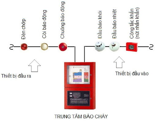
In this system it is possible to install push-button heat detectors. When a fire occurs, the output devices will act as horns, bells, and indicator lights.
2. The schematic drawing of the addressable fire alarm system
Addressable fire alarm system is a system consisting of devices installed on a signal line with different addresses. On a signal line, how many devices can be installed will depend on how many devices can be supported by the type of fire alarm cabinet.
Addressable fire alarm systems operate more flexibly than conventional fire alarm systems. In particular, we will know exactly where the fire occurs because each smoke, heat or push button has a unique address.
For this system, the output devices can be programmed as desired by the programming software.
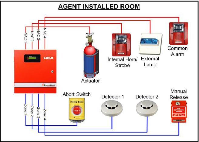
The addressable fire alarm system can be connected to a computer to monitor the operation of the equipment.
It is possible to connect multiple fire alarm cabinets together to manage on one computer. With flexible features that help to customize the addressable fire alarm system to be suitable for use in large projects with a large number of devices.
For an addressable fire alarm system, when an input is affected, we can program any control device to operate according to needs. From there, it helps to monitor the device’s activity on the computer without having to go to the cabinet. At this time, the software on the computer will help us connect directly to the fire alarm cabinet and operate as on the real cabinet.
How to install a fire alarm system according to the principle diagram
From the drawing of the schematic diagram of the fire alarm system, you need to install it according to the following instructions:
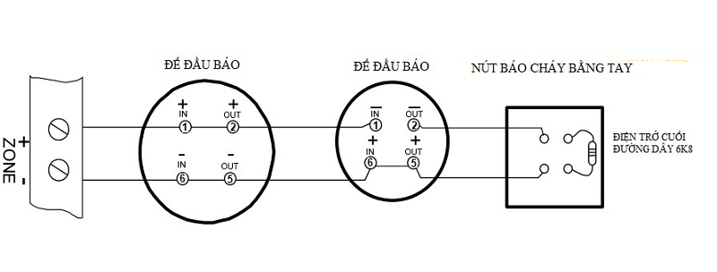
1. Step 1: Wire the detector base
According to the connection positions on the detector base, it is necessary to wire the correct polarity of the detector base and the resistor. On the base of the detector there are pins 1, 2 and 5, 6. In which pins 1 and 6 are incoming pins and pins 2 and 5 are pins going to devices.
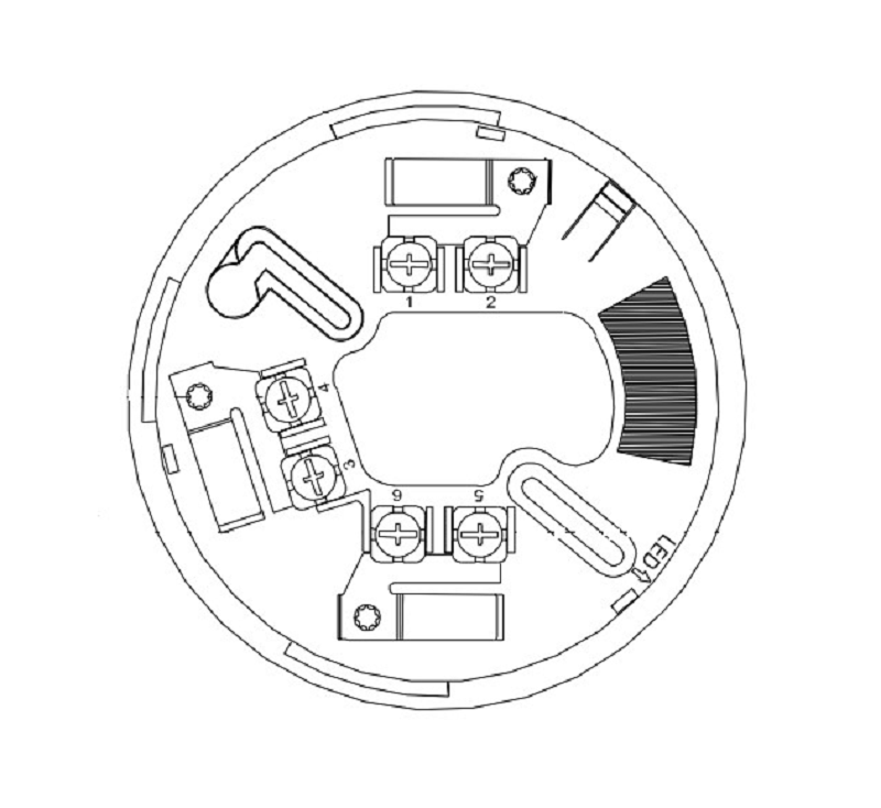
2. Step 2: Connect the detector base and manual fire alarm button to the Hochiki HCV-8 . fire alarm panel
Connect the detector to the central fire alarm cabinet. Then continue to connect the fire alarm button and connect the resistance at the end of the wire and twist the resistors into the two ends of the wire.
The manual fire alarm button can be connected with the detector zone or independently on a separate channel. Subsequent zones will do the same for zone 1.
3. Step 3: Insert the detector into the detector base
There is a small brick on the body of the detector and the base. When installing, people should pay attention to these 2 tiles to connect together and create a straight line.
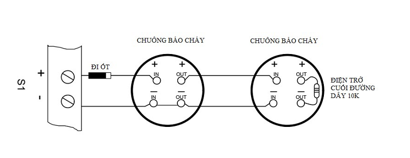
4. Step 4: Connect the bell and light to the Hochiki HCV-8 . fire alarm panel
When connecting to the Hochiki HCV-8 fire alarm panel, it is necessary to conduct the polarization of the bell because the bell is not polarized. This is done by installing a bias diode and installing a resistor at the end of the line for the bell line (must use the correct resistor with a value of 10K). The bell wire connected to the S1 line is polarized + and – .
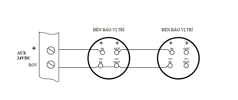
The position indicator light is a non-polarized indicator light, so when connecting the Hochiki TL-14D position indicator light, the lamp is connected to the power cord in the style of a plug, the position indicator wire is connected to the AUX + and ROV pins.
6. Step 5: Connect 220VAC mains power and 24VDC backup power to the fire alarm center
After completing steps 1 to 4, it is necessary to check once again to ensure that the wires are properly connected before supplying power to the system.
- Connect the 220VAC mains power to the terminal block
- Connect the backup battery power supply
Instructions for reading the schematic diagram of the fire alarm system
Gas fire alarm systems are usually designed according to VN standards TCVN 5738 – 2001 & TCVN 3890 – 200
– The fire alarm center is responsible for receiving signals from fire detectors and processing signals, controlling output devices such as light bells, exhaust valves, etc.
– The fire alarm zones are displayed through the pre-installed channel and the zones are displayed on the LCD screen of the control center.
– The detectors used by everyone are smoke and heat detectors, etc. These detectors will be effective when there is a fire, many detectors have transferred information to the processing center.
– Alarm devices in the system are whistles, flashing lights, bells, etc. These types of devices will emit sound and flash when there is a command from the information processing center.
– Emergency switch: includes 2 types: 1 type works to activate the fire alarm system manually.
– The devices appearing in the schematic diagram of the fire alarm system are connected to each other by cables in galvanized pipes.
– Power supply for the center 220VAC, when the central power fails, will automatically switch to the mode of taking backup power from the battery.
– Control center (4,8,16…channels, 2,4,8 Loop…) is located at the guard house
– Explosion-proof fixed heat detector designed to meet the building protection range.
– Flashing siren and buttons are arranged in an easy-to-observe area to make it easy for users to manipulate.
Contact us today for a free consultation and answer at:
Contact information P69 – M&E Contractor
Address: No. 6/165C Xuan Thuy, Cau Giay District, Hanoi
Website: https://p69.com.vn/
Hotline: 02437688156 – 0965937799
Email: kd@cokhip69.com.vn
Facebook: https://www.facebook.com/p69nhathaucodien
LinkedIn: https://www.linkedin.com/in/congtyp69/
Youtube : https://www.youtube.com/channel/UCOUwCnE5iGj8iqe_ZIUM7oA

