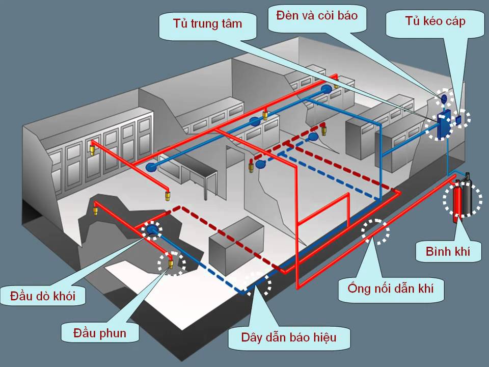
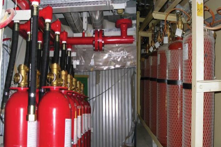
Installing FM gas fire extinguishing system is used in many fire fighting applications because of its safety. The automatic fire extinguishing system FM gas reacts with the combustible substance to absorb the heat of the fire. Prevents the chemical reaction of the combustion chain reaction. But especially FM gas does not reduce the amount of oxygen in the air as low as the CO2 system. So there is still oxygen in the room and it doesn’t cause asphyxiation. Does not affect people remaining in the room when the spray system discharges.
Requirements to ensure when installing FM gas fire extinguishing system
Based on the fire prevention and fighting laws on “Regulating the management of the State for fire prevention and fighting”, the following standards are applied to design the automatic fire fighting system:
– TCVN 2622-1995 – Fire prevention and fighting for houses and works – Design requirements
– TCVN 5760-1993 – Fire fighting systems – General requirements for design, installation and use
– TCVN 7161-9-2002 – Gas fire extinguishing system – System design properties
– TCVN 5738-2001 – Automatic fire alarm system – Technical requirements
– NFPA-2001 – Standard for clean gas fire extinguishing systems
– NFPA-70 – Standard for electrical system design
– NFPA-72 – Standard for automatic fire alarm system design
Install FM-200 . gas fire extinguishing system
The installation of fire protection equipment in the FM200 gas fire extinguishing system is quite complicated, requiring a specialized design and installation facility to take care of operations to minimize possible risks. for fire protection systems. The specific installation steps proposed by P69 company are as follows:

1. For electrical control head and cable
The structure of the control head is electrically actuated and the cabling is mounted directly on top of the tank. This device has the function of receiving control signals transmitted from smoke, heat and fire detectors, etc. or directly from the control cabinet to activate the system operation. There is also a mechanical control head that is activated when a lever operation is performed. This type of head has the ability to automatically ventilate to prevent cases of gas escaping from the tank.
2. Control switch
The operating pressure is based on the system pressure generated by activating or deactivating the electrical signal transmitted to the control cabinet.
3. Control cabinet
Designed according to certain standards, ensuring stable operation mode
4. Cable pulleys
Used to change the cable direction without affecting the cable operation.
5. Smoke Detector
Smoke detectors are ion, optical, thermal… according to Kidde Fire Protection, UL standards. Listed, FMRC and/or LPCB.
6. FM-200 . Fire Extinguisher
Contained in a steel tank in liquid form with a pressure of 25 bar at 210C along with Nitrogen. Each tank comes with a pressure gauge, cover, and a connection port for connection to the attached gas trigger hose. Besides, it is also designed by safety lids to cover the outlet and jack of the tank when not in use. In addition, this device is also attached to the purpose of preventing uncontrolled gas discharge.
7. Fm200 . fire fighting system bracket
Made of steel. It is specially used to fasten the tank to the wall vertically or horizontally.
8. Cable Drawer
Use the cable to activate the system. In the event of a fire, use a steel lever to break the glass in front of the cabinet, and pull the handle out of the cabinet.
9. FM-200 . gas
Is led from the tank to the pipe system through flexible hoses with sizes of 40, 50, 65 mm inner diameter, and made of rubber. It is specially used to connect the exhaust system to the outlet on the valve of the fm-200 . gas tank
10. Fire sprinklers
Designed to discharge air directly from the ceiling, thus minimizing the possibility of damage to the roof, so it has the effect of injecting air into the area to be protected.
Location of installation of control system equipment
– Fire control cabinets are located in front and outside the fire room.
– Smoke detectors, heat detectors are calculated and installed according to tcvn 5738: 2001. Installed inside the fire room.
– Exhaust trigger button installed at the entrance and outside of each fire room, 1.25m from the floor.
– Push button to delay release of gas installed at the door and outside of each fire room, 1.25m from the floor.
– Fire alarms, whistles/exhaust lights, installed at the entrance and outside of each fire room. 300mm distance.
– The warning board is located next to the fire control cabinet.
Advantages of FM-200 . gas system
Compared to CO2 or Argonite that need to evacuate people immediately when spraying, FM-200 is very safe. When FM-200 is sprayed, people can still breathe and take the necessary fire remedial measures.
Therefore, FM-200 is used in areas of control rooms, data processing, aircraft cabins, medical equipment areas, high value industrial equipment, libraries, museums, etc. art galleries, soundproof rooms, storage areas for combustibles, etc. are areas that are often occupied by people.
Compared to the Sprinkler system which takes nearly 10 minutes to activate the system, FM-200 takes only 2 minutes to activate. This helps to minimize possible damage. Moreover, the downtime for post-fire recovery of the sprinkler system is 16 days, while that of the FM-200 system is only 1 day.
Thus, the cost of using FM-200 is cheaper than CO2, Argonite due to less equipment, safer for users than CO2, Argonite when operating pressure is lower and does not cause asphyxia, safer for equipment than with the sprinkler after the system has activated. Both technically and economically, FM-200 brings convenience to the user. Therefore, FM-200 fire extinguisher has become an important fire extinguishing agent in industry.
Test procedure for automatic gas fire extinguishing system FM200
The FM200 gas automatic fire suppression system test procedure includes the following steps:
1. Fire detection
When a fire is released, smoke/heat will be generated and spread in the air. Smoke/heat detectors sense smoke and send an alarm signal to a conventional fire control panel. In other cases, the fire alarm system has not been able to detect the fire but people have seen it, they can press the push button of the Exhaust Process Activation Complex (FAS260-PS-28V-RD) to provide fire information to the fire alarm system. fire control panel (FAS-EP203).
When testing using smoke/heat to test directly on the detector to check the ability of the fire detector to receive and process the fire alarm signal of the fire alarm center, the center will give out a fire alarm signal with a bell. Next, try the second detector, the fire alarm center gives a fire-fighting signal by flashing siren.
2. Alarm signal
When receiving a fire alarm signal, the automatic fire control center will issue an alarm signal (prepare to release gas) and at the same time begin to calculate the delay time. The above alarm signal will include: audible alarm signal (alarm bell) and sign signal (air discharge indicator light comes on).
3. Emergency exhaust stop mode.
There are two reasons for the existence of an emergency stop button: first, when FM200 exhaust gas can be dangerous to people, and second, the process of replacing FM200 gas is relatively expensive. So when someone realizes that the fire alarm signal is a fake signal or, during the delay, realizes that the fire is no longer dangerous or has been extinguished… they can press the emergency stop button to stop it. prevent exhaust gas.
4. Activation and gas injection process.
When the fire alarm center calculates the alarm delay time, it will issue a command to activate the exhaust gas. The trigger signal is sent to the solenoid valve (on the trigger tank) the gas from this bottle will open the nominal zone selection valve, and then continue to open the large FM200 gas bottle below, FM200 gas is discharged into the manifold. , through the zone selection valve opened & into the area to be extinguished. (During the test do not connect the trigger valve to the gas tank).

5. Activated by push-button release (FAS260-PS-28V-RD)
– The person in charge of operating the fire fighting system presses the FM200 spray activation button outside the room door – The main electric siren sounds on the center.
– The electric horn in the warehouse will sound an alarm. (If loudspeakers are used here, the pre-existing audio tape will automatically announce alarm information through the loudspeaker.)
– Fire alarm signal is transmitted continuously.
6. Manual activation: Choose 1 of 3 methods below
– Press the exhaust process activation combination (FAS260-PS-28V-RD).
– Press the “Manual extinguishant release” button on the cabinet (FAS-EP203).
– Slide the release lever on the priming gas bottle (CO2054-CS-020-SP).
Working principle of FM-200 . gas fire extinguishing system
– FM-200 works with combustibles, absorbs the heat of the fire to prevent the chemical reaction of the chain reaction, but especially does not reduce the amount of oxygen in the air as low as the CO2 system, so There is still oxygen in the room and it does not cause asphyxiation, does not affect people remaining in the room when the spray system discharges.
– FM 200 gas will be compressed as a liquid in a pressure vessel along with N2 gas to ensure that when spraying, FM-200 gas will be pushed out to cover all the space in the room to be extinguished through the pipeline system. and 360° or 180° open air nozzles as gas.
– The amount of FM-200 gas must be carefully calculated to ensure the necessary spray density, not exceeding the allowable threshold for an area with people of 10%.
– The diameter of the air pipe and the nozzle size are accurately calculated by the software support, so that the exhaust time of the system is not less than 5 seconds and not more than 10 seconds.
Contact us today for a free consultation and answer at:
Contact information P69 – M&E . M&E Contractor
Address: No. 6/165C Xuan Thuy, Cau Giay District, Hanoi
Website: https://p69.com.vn/
Hotline: 02437688156 – 0965937799
Email: kd@cokhip69.com.vn
Facebook: https://www.facebook.com/p69nhathaucodien
LinkedIn: https://www.linkedin.com/in/congtyp69/
Youtube : https://www.youtube.com/channel/UCOUwCnE5iGj8iqe_ZIUM7oA

